X-Band (WX & EO Satellites)
On this page you will find some information about the X-Band hardware that I’m using. It includes some details about my self-designed downconverters, the LNAs that I’m using as well as the feed configurations that I have tested so far. My main focus on the X-Band is the 7700 – 8400 MHz range which is also known as the upper end of the lower X-Band. This portion of the band mainly contains earth observation and weather satellites. Most of the satellites are in a Low-Earth-Orbit (LEO) but there are also a few in geosynchronous and high elliptical orbits.
Compared to L-Band and VHF satellites the data rates of the downlinks on the X-Band are considerably higher and therefore the resulting pictures are of much higher quality. Depending on the data rate the signals vary in bandwidth and strength.
Downconverter
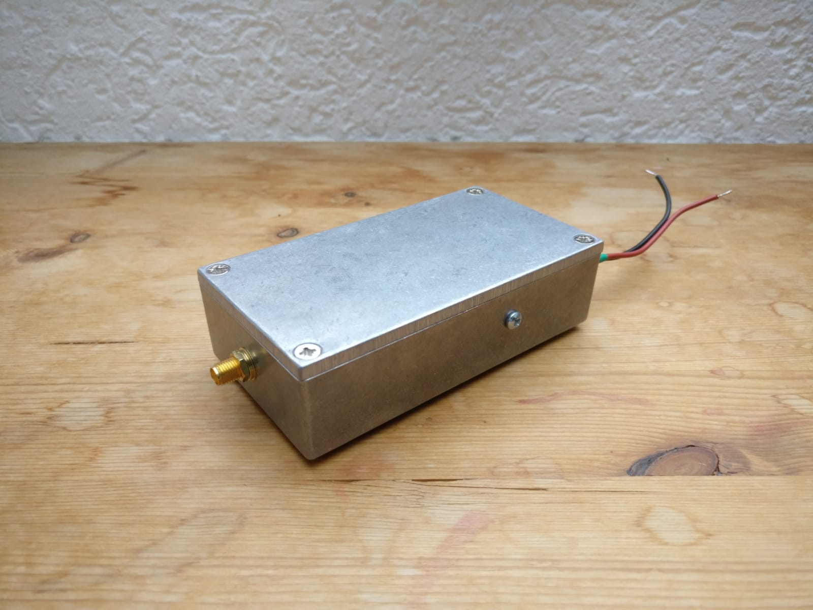
X-Band WX and EO Satellites transmit in the range of 7700 to 8400 MHz. Most amateur friendly receivers that are available today are not capable of receiving any signals in this range directly. That is where a downconverter comes into play. The downconverter takes the X-Band signal and converts it down into the L-Band range (or lower) which means that any receiver capable of receiving L-Band frequencies (provided it has enough bandwidth) can be used for recording these satellites.
I designed my own downconverter for this purpose with the following specifications:
- input frequency range: 7500 – 8500 MHz
- four different pre-programmed LO frequencies to avoid losses on the IF side
- conversion gain of +10dB at 7800MHz
- IF frequency range: 500 – 1500 MHz
- single +12V power supply input with optional Bias-T option
- low noise components for low noise RF performance
This converter has been proven to work really well with many different types of setups. From small offset dishes all the way up to large prime focus dishes. The only requirement is a good low noise amplifier with plenty of gain and ideally a low noise figure for optimal performance.
The full datasheet for my LNC may be found here.
Other converters or LNBs may be used.
(Low Noise) Amplifiers
Every downconverter (including mine) requires a good amplifier in front of it directly behind the dish feed to boost the signal level. If you are using a LNB it is not necessary as they already have one built-in.
The most common amplifiers in use for this purpose right now are surplus units made by MiTeq in the USA. These can sometimes be found on eBay for reasonable prices or other microwave flea markets. Other more expensive amplifiers may be purchased from Lotus Communication Systems (such as a couple of LNA2G18G units in series) or from Kuhne Electronic in Germany.
Here is the MiTeq amplifier I am currently using in my personal setup:
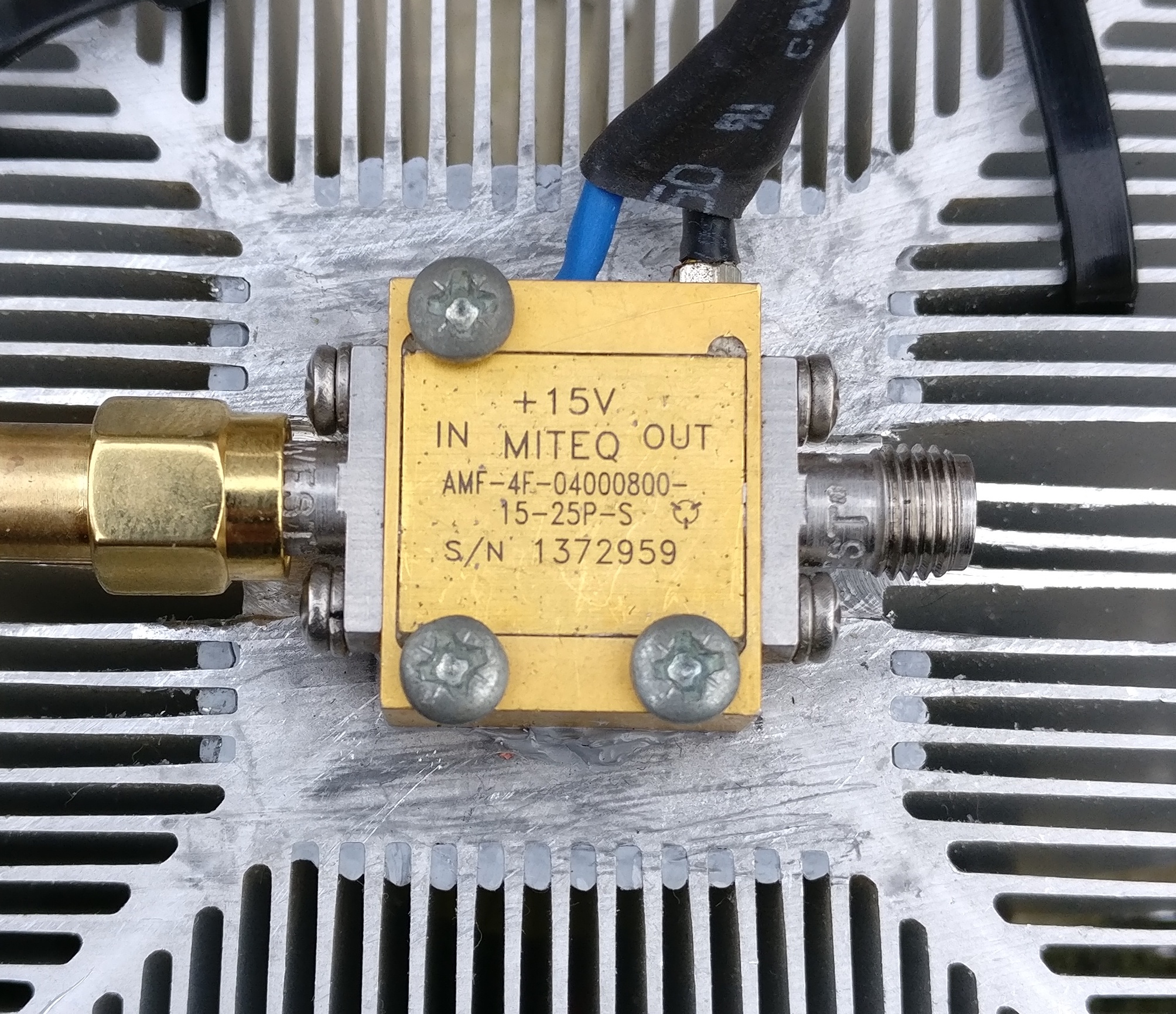
This unit features about 36dB of gain with a noise figure of around 1.5dB.
Dish Feeds
On the X-Band dish feeds are usually made with waveguides. Most equipment uses coaxial connectors, usually SMA or N types. That is why you need a coax to waveguide transition. The easiest way to build one is to use a piece of 28mm copper pipe, a pipe cap of the same size (or just flat copper plate) and your favorite coaxial connector (either SMA or N type). It should look something like this:
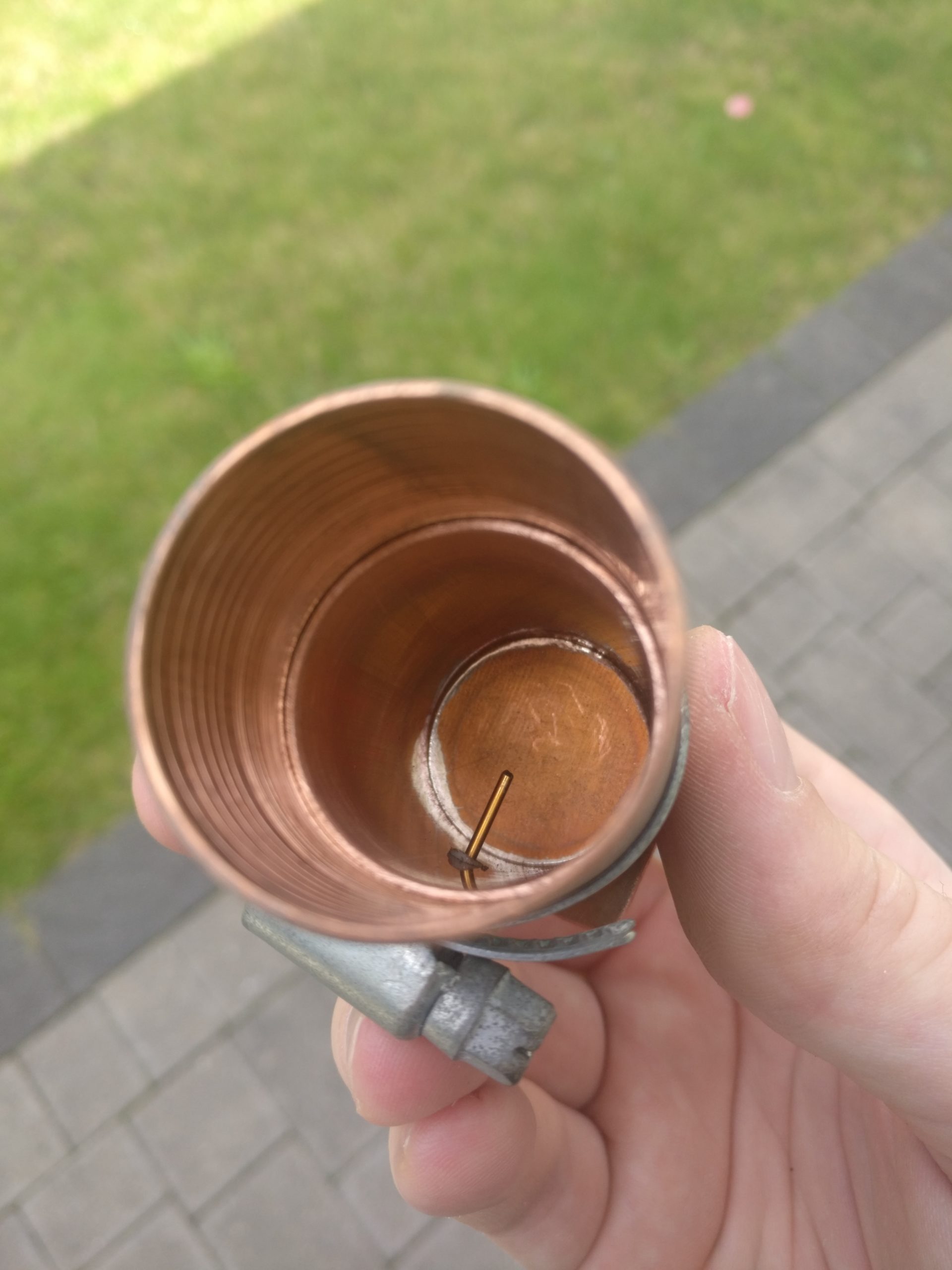
The idea of these coaxial to waveguide transitions is very simple. A probe (center pin of the connector) gets inserted into the waveguide with a length of quarter of a wavelength (around 10mm on 8GHz). This probe is placed quarter of wavelength away from the back (closed end) of the waveguide. The actual length of the waveguide itself is not too critical but it should be at least half a wavelength long at the lowest frequency of interest. I usually build them at lengths of 20 – 25 cm.
The next important part of receiving satellite signals is the depolarizer. Pretty much all satellites on the X-Band use circular polarization while this simple waveguide transition above is linearly polarized. That means the circular signal somehow needs to be converted into a linear polarized signal. Here is where the depolarizer comes into play as it fulfills exactly this purpose. The easiest way to convert a circular polarized signal into a linear one is by using a piece of Teflon (around 53x26x3mm in size for 28mm copper pipe). This piece of Teflon gets installed right at the mouth of the waveguide so that only a tiny bit of it sticks out (a few mm at most).
The angle relative to the probe is very critical, it always has to be 45°. At the same times this means the Teflon piece may be inserted in two different ways since there are exactly two possibilities to install it in a 45° angle. Which way around determines the actual polarization as seen in this picture:
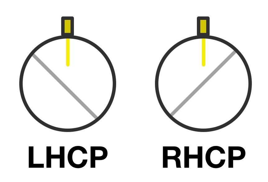
Note that this diagram already takes the mirror effect of the dish into consideration. If you want to build a feed that is not meant to be used with a dish you may flip the polarization around by 180°.
These Teflon depolarizers are by far the easiest and cheapest option. Other options may be the squeezed tube depolarizer (narrow bandwidth) or a Septum feed. The latter one is quite hard to build if you do not have access to precise metal working machinery.
The final part of each dish feed is the choke which is used to pick up as much signal from your dish as possible to make it more efficient. Each dish type requires a different design as it mostly depends on the f/D ratio of the reflector. On prime focus dishes with a rather low f/D (below 0.5) the most commonly used chokes are the VE4MA or chaparral style. For offset dishes (f/D of 0.6 or higher) the W2IMU design may be preferable.
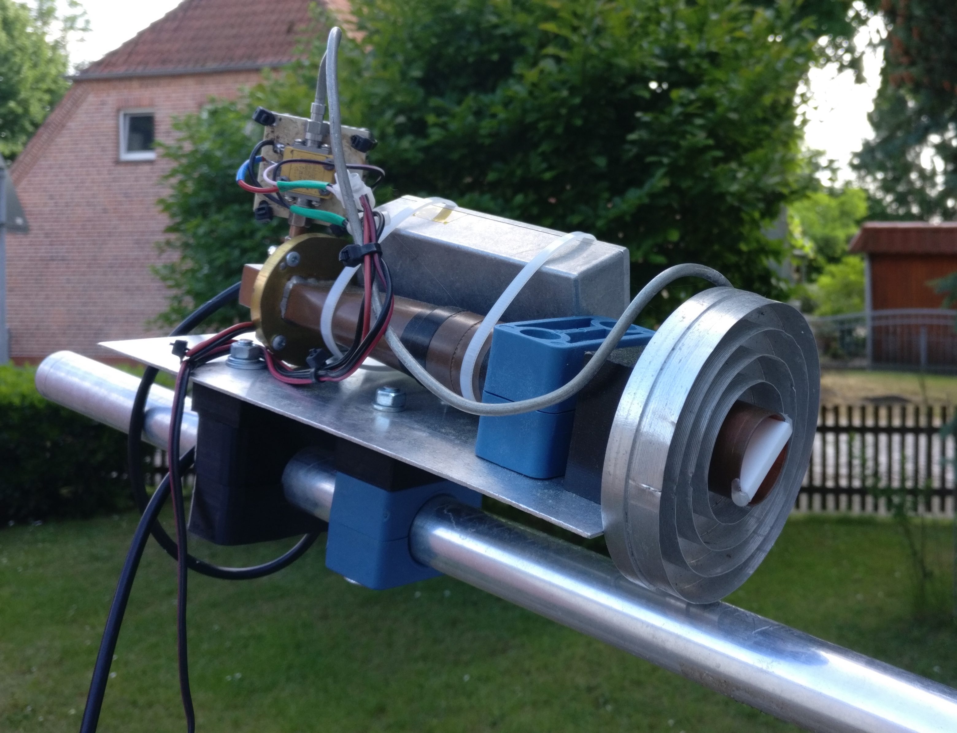
A chaparral style choke in use with a prime focus dish.
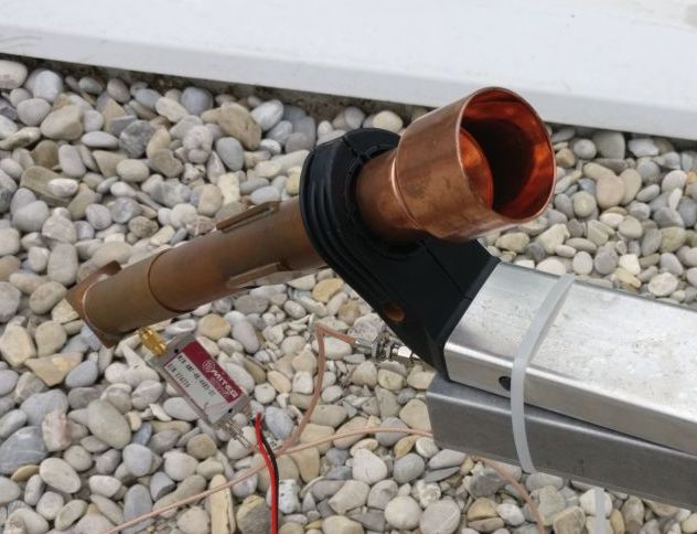
A W2IMU style choke in use with an offset dish.
An excellent source for more information on dish feeds are the publications of Paul Wade W1GHZ. In there he nicely shows the differences between each design with efficiency calculations in regards to the f/D ratio. For prime focus dishes you may find this document helpful and for offset dishes this one is worth reading through.
If you have any questions on this topic feel free to contact me by email (arved(at)m0kds.com) or on twitter and I will try to get back to you as soon as possible. I will continue to update this page as time goes on. Current revision: 07/2022


